QIDE JSON
The Quantum Integrated Development Environment uses a JSON document to describe a circuit. The syntax of this document is described in the chapters listed at left under this topic heading.
QIDE JSON Circuit Definition
A QIDE JSON document defines a quantum computing circuit - any circuit diagram can be represented in QIDE JSON. The document consists of a top level set of properties that describe the quantum circuit (i.e. the qubit count) along with an array of gate objects. Here's a simple example of a Bell state circuit with two qubits:
{
  "qubit_count": 2,
  "gates": [
    {
      "gate_type": "H",
      "target_qubits": [ 0 ]
    },
    {
      "gate_type": "CNOT",
      "control_qubits": [ 0 ],
      "target_qubits": [ 1 ]
    },
    {
      "gate_type": "M",
      "target_qubits": [ 0, 1 ]
    }
  ]
}
Top Level Properties
qubit_count: (Number) The number of qubits in the circuit.ignore_danger: (Boolean) If thequbit_countis greater than the warning default (currently 16), then this flag must be set totruein order for the circuit to be run. State vectors grow exponentially based on thequbit_counttherefore it is easy to use up all memory simply by setting the number of qubits too large.gates: (Array) The list of Gates in the circuit.use_2_bit: (Boolean) Only used for Bloch diagrams as it provides qubit state values prior to being entangled.parameters: (Object) User defined properties that can be used in rvalue expressions (thervalue_exprproperty of a gate object). For example:{ "qubit_count": 2, "parameters": { "param1": 1.14159 }, "gates": [ { "gate_type": "R1", "target_qubits": [ 1 ], "rvalue_expr": "1.0 * param1 / 2.0", } ] }
Gate Object Properties
The following properties define the basics of a gate - the type and any control or target qubits.
gate_type: (String) One of any of the documented gate types such as standard gates.target_qubits: (Array) List of qubits to which the gate is applied.control_qubits: (Array) List of qubits that act as the controlling qubits. Note that only a single qubit can be specified as atarget_qubitwhen control qubits are specified.
R-value Options
The following properties are used in gates that require and r-value.
rvalue: (Number) A radian value used inRr-value gates. For example:{ "gate_type": "R1", "target_qubits": [ 1 ], "rvalue": 3.14 }rvalue_dyadic_denom: (Number) Used in conjunction withrvalue, this sets the r-value to the computation (rvalue* pi / 2 ^rvalue_dyadic_denom)rvalue_expr: (String) A mathematical expression that defines the r-value and can use parameters or built-in constants such aspi. These expressions are implemented using the meval Rust crate and its documentation can be referred to for more information.{ "gate_type": "Rx", "target_qubits": [ 1 ], "rvalue_expr": "pi / 2.0", }
Advanced Properties
adjoint: (Boolean) Iftruethen the adjoint (conjugated transpose) of the gate matrix is applied. This is used in "undo-ing" prior gates used to potentially measure a qubit in a different basis, and are set automatically in conjugate composite gates.rand_source_type: (String) Used in measurement gates to determine the source of the random numbers used to collapse a qubit's state. If set toRandRng, a software random number generator is used. If set toRandomSeedthe RDS Random Seed service is used.within_gates,apply_gates: (Array) Both arrays contain a list of gate objects and are used in composite gates.
Informational Properties
The following gates are used to document a circuit within the json document. They are not used in any calculations and may be set to whatever the designer wishes.
gate_name: (String) Can be used to name a gate.comment: (String) Can be used to describe or document a gate or block.
Standard Gates
Basic Gates
The following are the most common or well-known gates in quantum computing. All of these allow for any number of target_qubits.
I: Identity gate (this has no effect on a qubit but might be used for clarification)X: Standard X gateY: Standard Y gateZ: Standard Z gateS: Standard S gateT: Standard T gateH: Standard Hadamard Gate
R-value Gates
The following are R-value gates that require an rvalue (or rvalue_expr, rvalue_dyadic_denom) to be specified in the gate definition. For example:
{
    "gate_type": "Rx",
    "rvalue": 0.4,
    "target_qubits": [1]
}
R1: Standard R1 gateRx: Standard Rx gateRy: Standard Ry gateRz: Standard Rz gate
Controlled Gates
Note that any of the above gates can be controlled by simply specifying the control_qubits and a single target_qubit in the gate definition. However, the following are provided for compatibility and standardization with other systems.
-
CNOT: The controlled NOT gate. Note that this is identical to the following gate definition, where the 0 qubit is the control and the 1 qubit is the target:{ "gate_type": "X", "control_qubits": [0], "target_qubits": [1] } -
CZ: The controlled Z gate. Note that this is identical to the following gate definition, where the 0 qubit is the control and the 1 qubit is the target:{ "gate_type": "Z", "control_qubits": [0], "target_qubits": [1] }
Measurement Gates
Measurement gates collapse the state of a qubit. Refer to the rand_source_type gate object property to learn more about the randomness used to simulate quantum collapse.
MorMz: Measurement gate in the Z-basis.Mx: Measurement gate in the X-basis.My: Measurement gate in the Y-basis.Mz: Measurement gate in the Z-basis.
Miscellaneous Gates
SWAP: Swaps the two qubits specified intarget_qubits.
Composite Gates
Composite gates are gates that expand into a set of gates and therefore all composite gates can be constructed manually. However, particularly in the case of the CONJUGATE gate, composite gates are much easier to use.
-
CNOTChain: This composite gate creates a chain ofCNOTgates linking the qubits in thetarget_qubits. For example, thisCNOTChaingate...{ "gate_type": "CNOTChain", "target_qubits": [0, 2, 3] }...would expand to:
[ { "gate_type": "CNOT", "control_qubits": [0], "target_qubits": [2] }, { "gate_type": "CNOT", "control_qubits": [2], "target_qubits": [3] } ] -
CONJUGATE: This gate will:- Apply all the gates in the
within_gatesarray in the gate object. - Apply all the gates in the
apply_gatesarray in the gate object. - Apply the adjoint of all gates in the
within_gatesin the opposite order they were applied.
For example, this
CONJUGATEgate...{ "comment": "****** 110 => 1 ******", "gate_type": "CONJUGATE", "within_gates": [ { "gate_type": "X", "target_qubits": [2] } ], "apply_gates": [ { "gate_type": "X", "control_qubits": [0, 1, 2], "target_qubits": [3] } ] }...would expand to:
[ { "gate_type": "X", "target_qubits": [2] }, { "gate_type": "X", "control_qubits": [0, 1, 2], "target_qubits": [3] }, { "gate_type": "X", "target_qubits": [2], "adjoint": true } ] - Apply all the gates in the
QRNG E Gates
E Gates are versions of the standard gates that are driven by a quantum random number generator (QRNG). Thus, there is a real, unobserved, physical quantum state that is provided to the execution engine. For example, the Eh gate is a version of the H (Hadamard) gate wherein the qubit's superposition is inherent in the external (this is where the E comes from) state.
E Gates are r-value gates in that the r-value provided in the gate object defines where in the unit circle the external QRNG state is split.
E Gates can be applied before standard gates but not after, because standard gates are mathematical and obviously the mathematics cannot be routed back out to whatever quantum device is providing the E gate's state.
E Gates
The following are E gate versions of many of the relevant standard gates:
EorEx: Acts as measured X gate initialized with external quantum state.Ey: Acts as measured Y gate initialized with external quantum state.Ez: Acts as measured Z gate initialized with external quantum state.Es: Acts as measured S gate initialized with external quantum state.Eh: Acts as measured H gate initialized with external quantum state.
For example, the circuit below creates a 5 qubit system where each qubit is initialized by the external QRNG and given the rvalue is approximately pi for each, then each qubit is initialized with a 50/50 probability of being 0 or 1 in the basis specified by the E gate.
{
    "qubit_count" : 5,
    "gates": [
        {
            "gate_type": "Ex",
            "rvalue": 3.14,
            "target_qubits": [ 0 ]
        },
        {
            "gate_type": "Ey",
            "rvalue": 3.14,
            "target_qubits": [ 1 ]
        },
        {
            "gate_type": "Ez",
            "rvalue": 3.14,
            "target_qubits": [ 2 ]
        },
        {
            "gate_type": "Eh",
            "rvalue": 3.14,
            "target_qubits": [ 3 ]
        },
        {
            "gate_type": "Es",
            "rvalue": 3.14,
            "target_qubits": [ 4 ]
        }
    ]
  }
QWave Controlled Gates
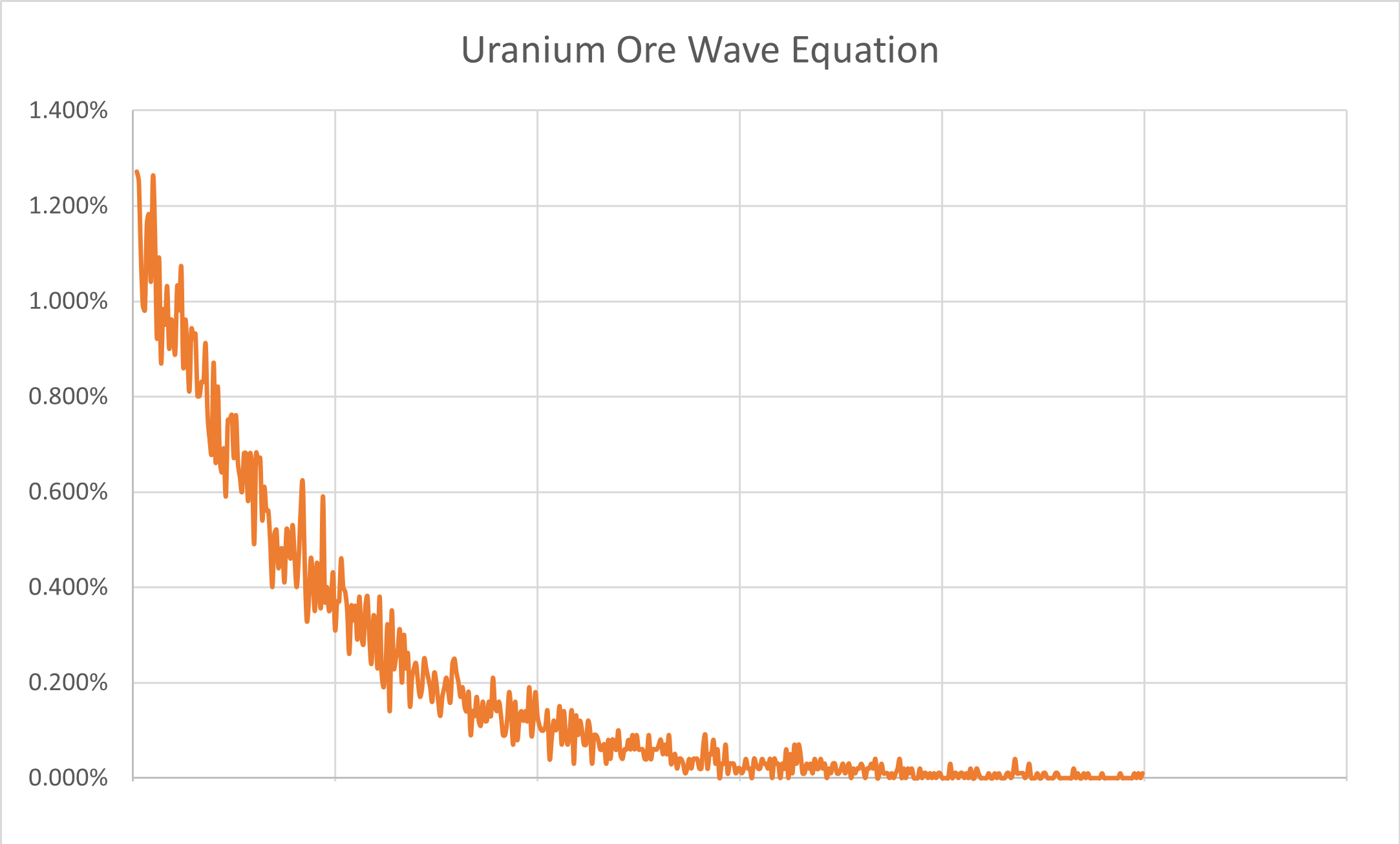
A QWave controlled gate encodes a wave function from an outside (real world) quantum state from some quantum system to one or more target qubits. For example, uranium ore emits a radioactive ion (which is a quantum event) at a rate shown in the graph below. The y axis is the probability, and the x axis is the time between emissions. There is a higher probability of emissions occurring rapidly and subsequently a lower probability that there is a significant long (in milliseconds) gap between emissions.
Encoding A Wave Equation To Multiple Qubits
One way (hereby referred to as ManyBits) we could encode the wave equation to multiple bits is to simply create a bit representation of the scaled emission time (the x axis above). For example, if we have a four qubit register and we want to apply an emission of 3 milliseconds, we would convert the 3 to binary 1100 (leftmost least significant bit), then apply a chosen gate to the first two qubits in the register. This is what that would look like in a circuit where X is the gate being applied:
{
	"qubit_count" : 4,
	"gates": [
		{
			"gate_type": "X",
			"target_qubits": [0,1,2,3],
            "qwave_control": "UraniumOre1:ManyBits"
		}
	]
}
Another way (hereby referred to as OneBit) we could encode the wave equation to multiple bits is to scale the number of bits to the x axis of the graph above and chose only a single bit based upon where the emission time landed. Considering a four qubit register again, a 3-millisecond emission time would convert to binary 1000 - the first bit is the only bit set because this is where a 3 would end up if the graph x axis were divided into four. This is what the same circuit would look like with OneBit set:
{
	"qubit_count" : 4,
	"gates": [
		{
			"gate_type": "X",
			"target_qubits": [0,1,2,3],
            "qwave_control": "UraniumOre1:OneBit"
		}
	]
}
To better illustrate the difference between encoding using ManyBits vs. OneBit, here is how the above wave equation would be encoded on a ten qubit register with these two encoding methods:
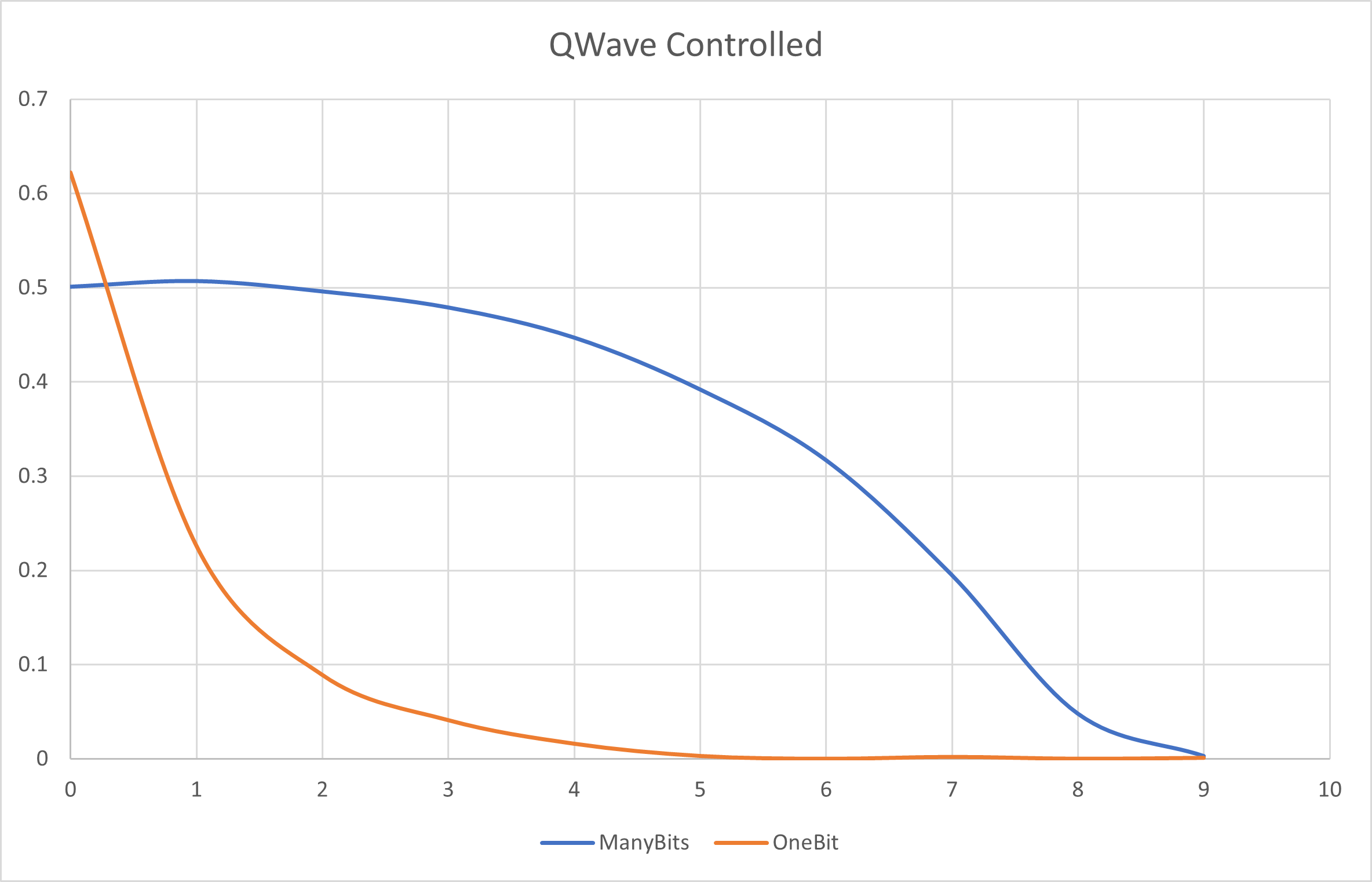
With the OneBit setting, one can see the probability of the given qubit (shown in the x axis) having the chosen gate applied to just it. With ManyBits, one can see the probability of any qubit having the chosen gate applied - the first qubit for example would have approximately a 50/50 probability.
Encoding A Wave Equation to An R-Value
To encode the wave equation into the phase of a single qubit, then the emission event can simply be encoded into the rvalue of the appropriate gate. In this case, the emission time is converted to a percentage (the x axis becomse a decimal number from 0 to 1) and then multiplied by the given rvalue. According to the graph above, this would mean a very low probability of the rvalue being multiplied by 1.0. This is what a rvalue encoded wave equation would look like:
{
	"qubit_count" : 2,
	"gates": [
		{
			"gate_type": "Rx",
			"target_qubits": [0],
			"rvalue": 6.2831853,
            "qwave_control": "UraniumOre1:RValue"
		},
		{
			"gate_type": "Ry",
			"target_qubits": [1],
			"rvalue": 6.2831853,
            "qwave_control": "UraniumOre1:RValue"
		}
	]
}
Entanglement?
Note that the next two sections are purely theoretical and should be prefaced with "arguably"...
ManyBits Entanglement
When a qubit register is encoded using the ManyBits method, then the entire register is immediately entangled since a single quantum state was used to set every qubit. Any (or all) qubits measured would have to collapse in a way that yields the bits within the original quantum state.
Temporal Entanglement
In the last example above showing rvalue encoding, notice that two quantum states are used one after another. This directly corresponds to two emissions and given the quantum state source (UraniumOre1) is the same, then these emissions are potentially entangled across time.