QWave Controlled Gates
A QWave controlled gate encodes a wave function from an outside (real world) quantum state from some quantum system to one or more target qubits. For example, uranium ore emits a radioactive ion (which is a quantum event) at a rate shown in the graph below. The y axis is the probability, and the x axis is the time between emissions. There is a higher probability of emissions occurring rapidly and subsequently a lower probability that there is a significant long (in milliseconds) gap between emissions.

Encoding A Wave Equation To Multiple Qubits
One way (hereby referred to as ManyBits) we could encode the wave equation to multiple bits is to simply create a bit representation of the scaled emission time (the x axis above). For example, if we have a four qubit register and we want to apply an emission of 3 milliseconds, we would convert the 3 to binary 1100 (leftmost least significant bit), then apply a chosen gate to the first two qubits in the register. This is what that would look like in a circuit where X is the gate being applied:
{
	"qubit_count" : 4,
	"gates": [
		{
			"gate_type": "X",
			"target_qubits": [0,1,2,3],
            "qwave_control": "UraniumOre1:ManyBits"
		}
	]
}
Another way (hereby referred to as OneBit) we could encode the wave equation to multiple bits is to scale the number of bits to the x axis of the graph above and chose only a single bit based upon where the emission time landed. Considering a four qubit register again, a 3-millisecond emission time would convert to binary 1000 - the first bit is the only bit set because this is where a 3 would end up if the graph x axis were divided into four. This is what the same circuit would look like with OneBit set:
{
	"qubit_count" : 4,
	"gates": [
		{
			"gate_type": "X",
			"target_qubits": [0,1,2,3],
            "qwave_control": "UraniumOre1:OneBit"
		}
	]
}
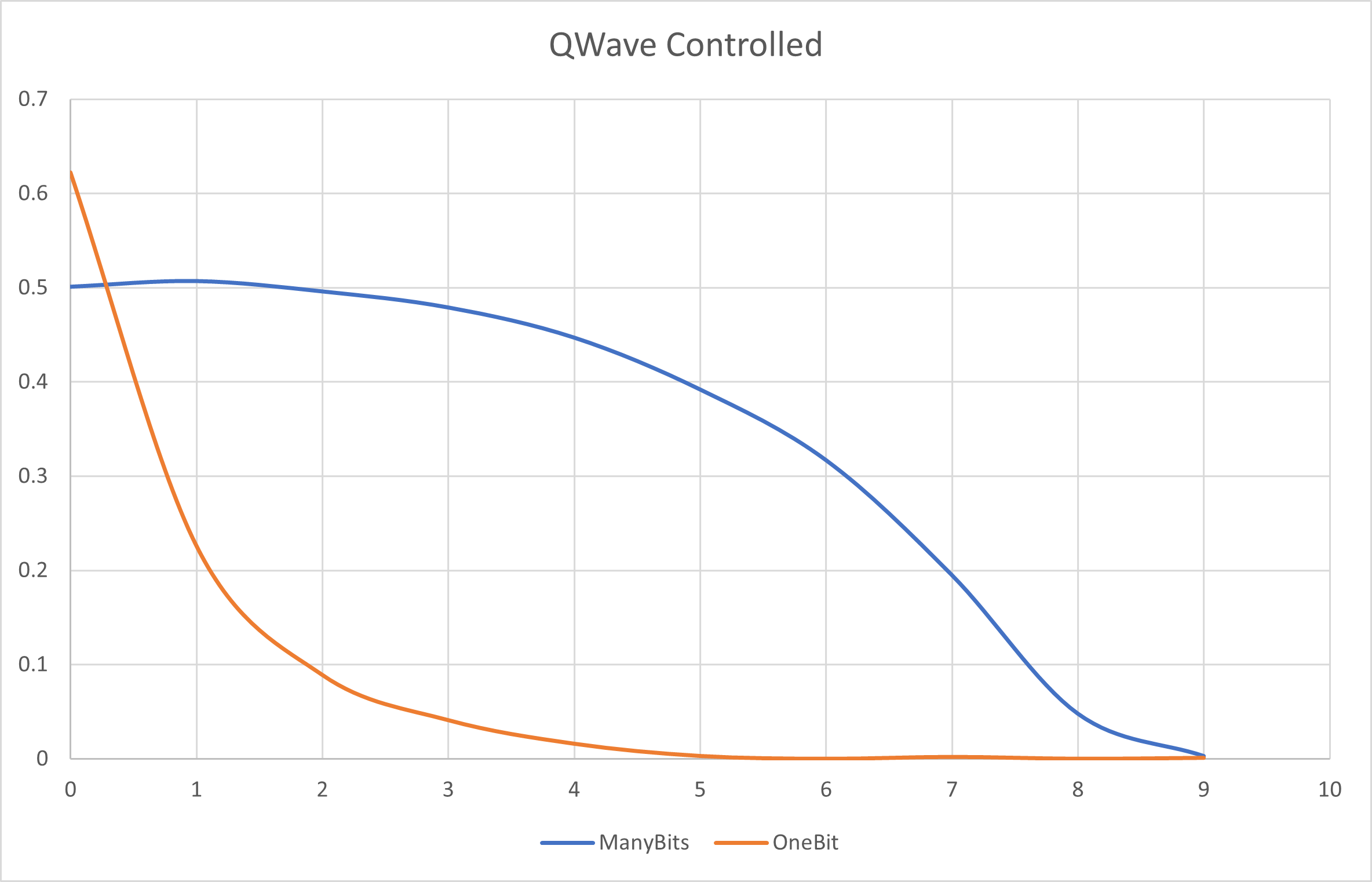
To better illustrate the difference between encoding using ManyBits vs. OneBit, here is how the above wave equation would be encoded on a ten qubit register with these two encoding methods:

With the OneBit setting, one can see the probability of the given qubit (shown in the x axis) having the chosen gate applied to just it. With ManyBits, one can see the probability of any qubit having the chosen gate applied - the first qubit for example would have approximately a 50/50 probability.
Encoding A Wave Equation to An R-Value
To encode the wave equation into the phase of a single qubit, then the emission event can simply be encoded into the rvalue of the appropriate gate. In this case, the emission time is converted to a percentage (the x axis becomse a decimal number from 0 to 1) and then multiplied by the given rvalue. According to the graph above, this would mean a very low probability of the rvalue being multiplied by 1.0. This is what a rvalue encoded wave equation would look like:
{
	"qubit_count" : 2,
	"gates": [
		{
			"gate_type": "Rx",
			"target_qubits": [0],
			"rvalue": 6.2831853,
            "qwave_control": "UraniumOre1:RValue"
		},
		{
			"gate_type": "Ry",
			"target_qubits": [1],
			"rvalue": 6.2831853,
            "qwave_control": "UraniumOre1:RValue"
		}
	]
}
Entanglement?
Note that the next two sections are purely theoretical and should be prefaced with "arguably"...
ManyBits Entanglement
When a qubit register is encoded using the ManyBits method, then the entire register is immediately entangled since a single quantum state was used to set every qubit. Any (or all) qubits measured would have to collapse in a way that yields the bits within the original quantum state.
Temporal Entanglement
In the last example above showing rvalue encoding, notice that two quantum states are used one after another. This directly corresponds to two emissions and given the quantum state source (UraniumOre1) is the same, then these emissions are potentially entangled across time.